An Overview of Hazardous Exhaust Ductwork Construction and Material Selection

Constructing ductwork and fume hoods that safely remove hazardous exhaust is an underappreciated challenge. Part of the reason is because there is minimal guidance available for this process, including appropriate materials selection. As a result, laboratory professionals need more direction to help protect people and the environment.
Hazardous Exhaust Effluent
When selecting ductwork material, a critical consideration is the characteristics of the effluent that will be extracted. Effluent can be divided into organic and inorganic classifications and is delivered through ductwork as vapors, fumes, chemical gases, particulate matter, or smoke. The qualitative nature of effluent is categorized as an acid, a base, a solvent, or an oil. Once within the exhaust system, effluent is exposed to valves, dampers, connections, fan blades and connectors, fan motors (depending on configuration), equipment housings, sensors, and other electronic components. Depending on the materials and the concentration of effluent, degradation and failure of the system or its components could occur.
Failure of system components occurs through one or a combination of three methods: corrosion, dissolution, or melting. Corrosion, the most common, destroys metal by causing a chemical or electrochemical action. Minimizing its impact is key to the longevity of the system. Dissolution negatively affects surfaces by attacking plastics and coatings. Melting dissolves plastics and coating through excessive and prolonged temperatures. A failure of plastics or coatings through dissolution or melting exposes the base metal underneath, allowing for corrosion of the base metal.
It is important not only for the corrosive or caustic nature of hazardous effluent to be identified, but to be understood in terms of its effect on the material surface. The impact that effluent will have on the system fluctuates considerably based on several factors, including:
- Caustic nature of effluent and average operational temperature.
- Concentration and quantity of chemicals exhausted through the system.
- Ambient temperature and relative humidity of the space from which chemicals are extracted and the ceiling cavity into which ductwork passes.
- Reaction of effluent to condensation and other moisture sources.
- Length and configuration of exhaust runs. Round ducts are preferred because velocity is more uniform (effluent less likely to settle), and they withstand higher static pressures and seal more easily. Ducts from fume hoods, for example, should slope back to the hood to allow effluent that condenses to drain back to the hood.
- Interaction of effluent from different sources in a common system and their velocities.
- Quality of ductwork construction, including welds, joints, fabrication, and support elements. Given the aggressive nature of effluent, defects in system construction could allow effluent to collect or become a future point of failure.
In addition to the corrosive or caustic nature of exhausted effluent, other characteristics that influence the selection of duct material are:
- Procurement and installation cost.
- Expected system lifespan and need for modifications.
- Service, maintenance, and monitoring.
- Product availability.
- Material sustainability and energy footprint.
- Material compatibility with other systems and materials.
- Contractors and sub-contractors’ availability to properly fabricate and install the system.

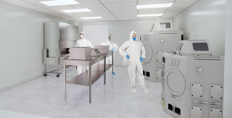
Glove boxes, like the example pictured here, allow researchers to extract hazardous materials in a safe environment. Pictured: Kenan Laboratories Renovation at UNC at Chapel Hill
Airflow and Velocity
The volume of exhaust flow and its velocity are also important. Lower velocities do not move potentially corrosive effluent as quickly, providing more opportunity for settling, especially in horizontal runs, directional changes, and transitions. Round ductwork velocity is more uniform and has minimal potential eddies or recirculation present as does rectangular duct. When velocities increase, frictional losses and associated fan energy also increase. A 40% increase in duct velocity will double the pressure drop and increase the fan energy associated with that section by nearly three times. The best approach is to balance duct velocity and fan power.
In most cases, velocities should be no lower than 500 feet per minute (FPM) for proper effluent movement. An upper limit of velocities in main system ducts is approximately 2,500 FPM based on considerations for static pressure, energy, and sound. Most of the focus on velocities is for design condition, but most of the system’s lifespan is spent at a much lower condition. For example, a range of 500-2,500 FPM results in a turndown ratio of up to 5:1 on a variable air volume system. A system sized in this manner can operate down to 20% of its design airflow while maintaining the minimum 500 FPM velocity.
Attention to duct velocities is not limited to the design of maximum flow conditions. Most modern designs implement variable air volume (VAV) control schemes. The system designer must consider velocities throughout the system’s airflow range and strike a balance between high velocities (frictional/energy losses) at maximum flow and low velocities at minimum flow. A velocity range of 500-2,500 FPM produces a turndown ratio of up to 5:1. Experience indicates that this is usually adequate for VAV fume hoods and other typical end-use devices.
Appropriate duct sizing and velocity largely depend upon the nature of effluent, duct type, and potential for contaminant deposition. Duct velocities and configurations should be designed to prevent the settling and accumulation of particulates and dry aerosols.

Researchers are shown working here with perchloric acid fume hoods with plastic-coated ductwork material.
Ductwork Material
Fume hood ductwork is generally constructed of stainless steel and G90 galvanized metal. Per the American National Standards Institute (ANSI) Code Z9.5, an analysis of the chemicals to be exhausted must be completed with the material selected based on resistance to the primary corrosive element. This is often difficult to assess during facility planning, design, and construction, but it is practically guaranteed that both chemical type and quantity will change over time. As such, many organizations install the most corrosive-resistant system available. An understanding of the materials’ qualities, however, will help determine the best and most cost-efficient products.
Materials used in each exhaust system need to be consistent, compatible, and in accordance with the International Mechanical Code and the American Conference of Governmental Industrial Hygienists. Consequently, laboratory planners and HVAC engineers should collaborate with safety officers and scientists to discuss options prior to material selection.
According to the National Fire Protection Association Standard 45, ductwork from chemical fume hoods and local exhaust systems are to be constructed of noncombustible materials, with few exceptions. Non-metallic exceptions require that the flame-spread index of the material be 25 or less and the smoke generation be 50 or less when tested in accordance with ASTM International Code E84 or ANSI/Underwriters Laboratories Code 723. The following list includes typical materials used in fume hood ductwork and their characteristics:
- G90 Galvanized steel. Subject to acid and alkali attack, particularly at cut edges and under wet conditions, this material cannot be field welded without destroying galvanization.
- Stainless steel. This material, while expensive, is optimal for working with solvents, but subject to acid and chloride compound attack, depending on nickel and chromium content of the alloy.
- Asphaltum-coated steel. While resistant to acids, this material is subject to solvent and oil attack. There is a high flame and smoke rating, and the base metal is vulnerable when exposed by coating imperfections and cut edges. Also it cannot be field welded without destroying coating and comes at a moderate cost.
- Epoxy-coated steel. Epoxy phenolic resin coatings on mild black steel can be selected for characteristics and applications. No single compound, however, is inert or resistive to all effluents. It requires sand blasting to prepare the surface for shop-applied coating, which should be specified as pinhole-free and field touch-up of coating imperfections, or damage caused by shipment and installation.
- Plastic-coated galvanized steel. This material is subject to corrosion at cut edges and cannot be field welded. It is easily formed and comes at a moderate cost.
- Fiberglass. This product is helpful with acid applications, including hydrofluoric acid. When additional glaze coats are used, this material could require fire-suppression provisions and associated pitching of ducts and drains. Special attention should be paid to hanger types and spacing required to prevent damage when choosing this material, as ducts could contain water.
- Plastic materials. Type 1 polyvinyl chloride (PVC) has a particular resistance to specific corrosive effluents and can be rigid or flexible. Limitations include physical strength, flame spread, smoke-developed rating, heat distortion, and high cost of fabrication. Special attention to hanger types and spacing is also needed to prevent damage. Chlorinated PVC has a similar performance, including better performance with flame spread and smoke development.
- Borosilicate glass. This material is intended for specialized systems with high exposure to certain chemicals, such as chlorine.
Safety First
The need to be meticulous when constructing ductwork and fume hoods for the removal of hazardous exhaust will always be the standard to protect people and the environment. The challenges associated with this work should not extend to finding guidance for the selection of materials and other related requirements for connected ductwork. Considering the characteristics of effluent, as well as the airflow and velocity of exhaust and the impact that these elements will have on materials, is an important baseline to appropriately understand the requisite safety involved.
This article was originally published in Labcompare.
Content Type
Published Articles
Date
February 08, 2022
Market
Practice
Laboratory Planning
Topic
Laboratory Design


